Essential Properties and Applications of Electrical Wiring Pathway Systems
Learning objectives
- Learn how to use NFPA 70: National Electrical Code (NEC) as a guide for proper conduit applications. References are based on the 2017 edition.
- Understand the physical properties of conduits and the benefits for different applications and that there are often multiple appropriate types of conduit available that can be used based on client needs and cost.
- Better understand the benefits and limitations of various types of pathways including busway, cable tray, wireway, surface raceways, power cable assemblies and open wiring.
There are numerous scenarios, details and options to consider when selecting the proper pathway for wiring solutions.
Conduit:
In the construction world, the term conduit is most often used to refer to a hollow tube that is intended to be a pathway for conductors or low-voltage cable.
It’s important to make a distinction between conduit and piping. While they both convey properties inside of them and often are available in similar sizes and shapes, conduits and pipes are two different items with different purposes and installation requirements. The term piping is most often meant to refer to a hollow tube or structure that is intended to be a sealed pathway to convey a liquid or a gas. Because of the properties of liquids and gases, piping can be run with very tight turns and can be routed from source to outlet without intermediate breaks in the system.
Figure 1: Conduit bodies provide access to internal wiring or cables and can be used to make radius turns. This shows a 90-degree change of direction, using a conduit body with rear removable cover. Courtesy: Peter Basso Associates Inc.
Unlike piping, conduit has distance limitations and requires planned “accessible pull points” to be able to install conductors and cables by pulling them into place. Conduit systems also require a larger turning radius at any changes of direction than is required by piping systems. Changes of direction are often accomplished using pre-made factory elbows or by bending the conduit in the field.
Based on requirements defined in NFPA 70: National Electrical Code, most conduit types are limited to 360 degrees of turns between accessible pull points. Items that are considered accessible pull points include: source distribution equipment, junction boxes, pull boxes, wireways, conduit bodies and equipment. Conduit bodies area a separate portion of a conduit or tubing system with integral removable covers that provide access to the internal wiring and in certain applications can be used to provide a tighter turning radius than an elbow or to provide pulling access to conductors or cables (see Figure 1).
Typical minimum conduit radii can be found listed in Chapter 9, Table 2 of the NEC. There are several factors that require larger radius turns including, but not limited to, long runs of conduit and special requirements for some types of communication cables.
The NEC contains descriptions, installation requirements and application rules for various types of conduits. Some of the more common conduit types are found in Table 1.
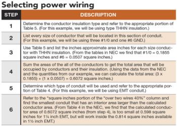
Table 1: Use this quick reference table to NFPA 70: National Electrical Code articles for commonly used pathways. Note: RMC type conduit includes several conduits constructed using different types of metal, all of which have unique properties and qualities. These include stainless steel, galvanized steel, red brass and aluminum. Courtesy: Peter Basso Associates Inc.
The various types of conduits have other attributes as well. Some conduits provide some corrosion —including rust — protection (e.g. polyvinyl chloride, aluminum rigid metal conduit, stainless steel RMC, red brass RMC and reinforced thermosetting resin conduit). Some offer various levels of mechanical protection (e.g. RMC, intermediate metal conduit and even electrical metallic tubing). Others are flexible and limit the transmission of vibrations or allow for some renovation work to be installed within existing building finishes (e.g. flexible metal conduit, liquid-tight flexible metal conduit and liquid-tight flexible nonmetallic conduit). Still other types provide some level of protection from water intrusion (ex: LFMC, LFNC and, to some extent, PVC and RTRC). See Figures 2 and 3.
To properly select the type of conduit to use, it is important to understand what material it’s constructed from, how it is terminated and coupled together, how difficult it is to install, cost differences for materials and installation labor and any other special properties it may possess.
Conduits with heavy (thicker) walls have threads cut into them to allow for fittings like couplers, lock nuts and bushings (RMC, IMC). These conduit types come pre-threaded and also require field–cutting threads as needed (see Figure 4). These conduits typically use fittings that screw onto their threads. When selecting which type of heavy wall conduit to use, several factors should be considered. Cost is always an important factor and conduits with thicker walls typically have a higher cost. Heavier–walled conduits also require more labor to install because they are more difficult to handle and support.
While conduits with threaded fittings do not ensure protection from water or liquid infiltration, they can perform better than conduits with mechanically attached slip fittings as would be used with EMT conduit. Conduits with threaded fittings also provide some level of protection from bug and rodent infiltration. Heavy–walled metal conduit with threaded fittings can provide an additional level of protection in areas where they might be subject to side impact from the movement of heavy equipment. A heavy-walled conduit also stands a better chance of maintaining its cross–sectional shape after an accidental impact.
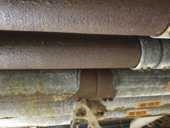
Figure 2: This photo shows the corrosive effects of a pool equipment room environment on EMT conduit and its fittings. Courtesy: Peter Basso Associates Inc.
The threaded fittings also can prevent conduits from separating at their couplings or other termination points on impact, which could expose and even damage the wiring inside if the conduit were to separate. Consider an example of a large feeder conduit run overhead in a parking area or loading dock. This may seem like a good place to save some cost and use EMT, but if something moving around below should snag itself on an EMT conduit, it takes less force to pull the conduit apart at its fittings than would a conduit system that uses threaded fittings.
Conduits with thinner walls, most commonly EMT, are too thin to have threads cut into them, so fittings are typically slid onto the outside of the conduit and terminated in one of several methods. A common termination method is compression fittings, which require a wrench around the fitting to tighten the screw portion of the fitting and collapse an interior ring onto the outside of the conduit to hold the fitting in place. EMT also can use set screw–style fittings, which contain screws that are perpendicular to the outside of the conduit and can be tightened down into the conduit to hold the fitting in place. EMT can save cost because it requires less material in its construction, is lighter and easier to handle and its slip–on type fittings typically install more quickly.
An understanding of the material and method of construction for each type of conduit is important to know when considering what environment the conduits will be subject to.
Metallic conduits are constructed of various metals that are suited for different applications. Galvanized steel RMC has a heavy wall and provides significant mechanical protection. Aluminum RMC conduits can be used in areas where strong magnetic fields require nonferrous metals, like an MRI. Aluminum RMC also can be used in environments that would corrode ferrous metal conduits. Stainless steel RMC can provide additional corrosion protection in certain environments. Red brass RMC is especially suited for contact with chlorinated water. This conduit is often used to feed wet niche light fixtures in areas that will be exposed to water.
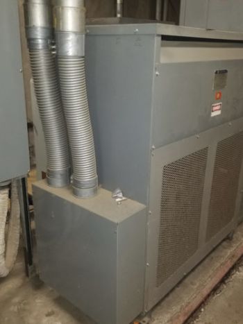
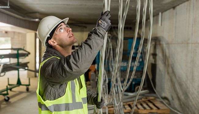
Figure 3: To limit the transmission of vibration generated by certain equipment, flexible conduit is used as the pathway for power wiring between the equipment and the rest of the distribution system. This shows a flexible connections at a transformer. Courtesy: Peter Basso Associates Inc.
Conduit types are not created equal. Not only are they constructed in different ways and of different materials, even when they share a common trade size, the interior dimensions are not uniform from type to type.
Tables for standard interior cross-sectional areas of different types of conduits are listed in Table 4 of the NEC. This table shows the internal diameter and total internal cross–sectional area of every trade size for every type of conduit. The table also calculates and lists the cross sectional areas of typical fill capacities that are outlined elsewhere in the code. The most common fill capacity is the 40% capacity that applies to the allowable conduit fill when more than two wires are in a conduit.
For an example demonstrating that trade sizes of different conduit types are not equivalent, refer to Chapter 9, Table 4 for comparison between Schedule 80 PVC and IMC conduits. A typical 1 ½-inch PVC Schedule 80 conduit provides 1.476 inches of interior diameter and 1.711 square inches of total cross sectional area, while a typical 1 ½-inch IMC conduit provides 1.683 inches of interior diameter and 2.225 square inches of total cross sectional area. If using the 40% fill column, IMC can support 0.890 square inches and PVC-80 can only be filled to 0.684 square inches.
To determine the minimum sized conduit that is needed for power wiring, refer to the tables contained in NEC Chapter 9. Table 4 lists the allowable fill capacities for typically available trade sized conduits for each type of conduit. Tables 5 and 5A indicate the nominal dimensions of insulated conductors, fixture wires and compact conductors. The steps below outline a typical installation. Note: This example does not address compact conductors. In this example, we’ll calculate the size for a feeder consisting of three #1/0 and one #6 GND.
Step Description
- Determine the conductor insulation type and refer to the appropriate portion of Table 5. (For this example, we will be using type THHN insulation.)
- List every size of conductor that will be located in this section of conduit.(For this example, we will be using three #1/0 and one #6 GND.)
- Use Table 5 and list the inches approximate area inches for each size conductor with THHN insulation. (From the tables in NEC we find that #1/0 = 0.1855 square inches and #6 = 0.0507 square inches.)
- Sum the areas of the all of the conductors to get the total area that will be occupied by conductors and their insulation. (Using the data from the NEC and the quantities from our example, we can calculate the total area: (3 x 0.1855) + (1 x 0.0507) = 0.6072 square inches.)
- Determine which type of conduit will be used and refer to the appropriate portion of Table 4. (For this example, we will be using EMT conduit.)
- Refer to the “square inches portion of the “over two wires 40%” column and find the smallest conduit that has an interior area larger than the calculated conductor area. (From Table 4 in the NEC, we find that the calculated conductor area of 0.6072 square inches (from step 4), is too small at 0.598 square inches for 1¼ inch EMT, but will work inside the 0.814 square inches available in 1½ inch EMT.)
In the example above, using EMT conduit requires 1½-inch trade size conduit, but if IMC conduit were appropriate and desired, this same feeder could be installed using smaller 1¼-inch IMC trade size conduit with a 0.659 square inches available area.
The previous example indicates how to determine the minimum conduit size for a particular type of conduit that contains more than one size conductor. The NEC also contains information in Informative Annex C that allows for a quick reference of conduit size. These tables do not take into account fill consisting of multiple conductor sizes, but can be used as a conservative sizing tool.
For example, a feeder will typically contain a ground conductor that is smaller than the phase conductors. In that case one could use the Annex C table and assume that the ground conductor is the same size as the phase conductors for a conservative conduit size.
Underground conduits often are used to get power and low-voltage services in and out of facilities, between buildings in a campus-type setting and also are used to feed equipment located on grade or out on a site. When conduits are installed below grade, the earth inherently provides a certain amount of protection for the conduits. If the earth above the conduits provides adequate protection, then these conduits can be directly buried in the earth and their primary function is as a pathway through the earth. Because of that, nonmetallic conduits are often used (refer to NEC Table 300.5 for required depths of conduits below grade).
Common nonmetallic conduits that are installed below grade are PVC, HDPE and RTRC. These conduit types are preferred because they typically provide a cost savings on material and on labor installation costs. Critical systems or power wiring that requires higher levels of protection from accidental damage from future excavation or drilling can be installed in metal conduits or encased in concrete in the form of a duct bank for additional protection. Conduits that are installed below grade also should be selected to maintain their integrity while being installed below earth. These conduits are often exposed to water, so PVC, HDPE and resin conduits often are selected because of their ability to maintain their integrity in this type of environment. There are also composite conduits, such as PVC coated steel conduits that combine the strength of metal conduits with some of the water protection of the PVC coating.
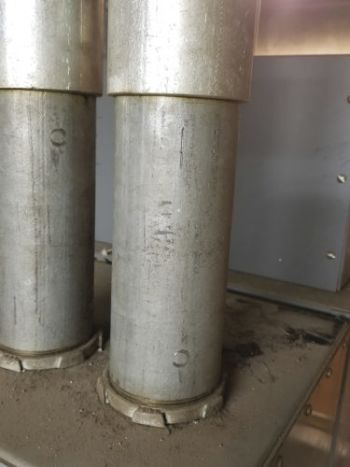
Figure 4: RMC conduit is terminated with threaded fittings. This photo shows the threads cut into the conduit and terminated in a piece of equipment using locknuts on the conduit threads.
Surface raceways:
Surface raceways are available in metallic and nonmetallic versions. These can be used for renovation work where surfaces, walls, or ceilings do not permit easy access for new recessed installations to take place. These are available in various configurations that accommodate a single pathway for either power or low-voltage work or divided pathways that allow for power and low-voltage pathways to be routed adjacent to one another within the same overall structure.
These systems also have options for surface mounting of the devices that they serve, including receptacles, network jacks and audiovisual connectors. Because these types of systems are exposed and surface–mounted, they require proprietary surface mounted fittings for all changes of directions and anywhere a tap is made that requires the pathway to branch off in more than one direction.
There is a vast array of these fittings that accommodate most situations. These fittings include boxes to connect to conduit, flat 90-degree elbows, internal 90-degree elbows, external 90-degree elbows, “T” fittings and just about any other type of special fitting you may require.
While these surface systems are often used for renovation work (see Figure 5), they also provide benefits and can be used as part of new construction. A new construction benefit is the ease with which additional conductors, cables and their associated devices can be added to a surface raceway system in the future. With some of the large dual pathway systems, it can be as easy as the contractor snapping off a blank cover, cutting it and snapping a device mounting plate in the new space.
Busway:
A busway system provides means to distribute power throughout a building or feeders or branch circuits within an area. Busways consist of an overall metal structure that provides a housing and protection for internal conductors. The conductors are typically solid and can be made of copper or aluminum and can consist of flat or round busses mounted inside of the metal housing.
Some advantages of this type of distribution are:
- The ability to get larger ampacities through a smaller cross-sectional area than conduit and wire.
- When using a plug-in style busway, power can be accessed at multiple points along the system.
- Larger busways can be routed vertically in multistory buildings allowing power to be “tapped” on each floor.
- Smaller plug-in style systems can be used overhead in machine shops or other areas where lots of equipment is located.
This type of system allows for multiple feeders to equipment and allows for simpler changes that may be required by new or relocated equipment. Very small systems can be used in data centers to provide branch circuit taps as required to feed network equipment. High–ampacity busways also can be used as part of substations to connect parts together without a need for multiple conduits and conductors between sections.

Figure 5: This photo shows surface-mounted raceway used in a lab renovation. This type of system can be mounted on an inaccessible concrete wall and also provides future flexibility which is desirable in a lab environment. Courtesy: Peter Basso Associates Inc.
Cable tray:
There are various styles of cable tray. Some types can be partially enclosed, while others use a very open support structure. Cable trays come in a multitude of sizes and configurations. Cable trays are commonly used as means of gathering up a large quantity of low-voltage cables along main routes and getting them back from devices to a main source.
Network cables lend themselves nicely to the use of cable trays. The tray system can be routed along a common route where all of the independent cables can gather together and make their way back to a network closet.
It is important to understand the space that open cables are routed through. For example, cables that are routed through a space that is designated as an air plenum are required to have insulation and jacket that is specifically listed to meet the requirements of an environmental air plenum. Cable trays allow supports and paths for future cable installations without the introduction of new hangers and supports. Cable trays can also be used to route and support power conductors. Conductors must be specifically listed for use as Type TC tray cable. See Table 2.
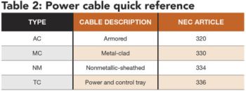
Table 2: This provides a reference table to NEC Articles for commonly used power cables. Courtesy: Peter Basso Associates Inc.
Power cable assemblies:
For commercial building applications, there are various types of cable assemblies made up of power conductors. These cable assemblies are available for everything from branch circuits up to large feeders. Common types of this cable are type MC and type AC. These cables can be installed concealed within construction finishes or exposed and can be installed in cable trays.
When run independently, unless otherwise listed, both MC and AC cables require a support within 12 inches of every outlet box, junction box, cabinet or fitting. AC cable requires supports every 4 ½ feet (NEC Article 320) while MC cable requires supports every 6 feet. The NEC lists more permitted uses for the MC cable than for AC cable. Both of these solutions typically provide a cost savings over conduit and conductors in many types of applications. However, these cables do not allow for additional conductors to be installed inside of them in the future and many people feel that they don’t look as neat and organized as a conduit solution.
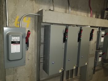
Figure 6: Wireways can be used to serve many purposed in an overall raceway system. This photo shows a wireway being used to tap an internal feeder to feed several motor controllers and safety switches. Courtesy: Peter Basso Associates Inc.
For dwelling unit applications, power wiring is typically accomplished using NM type cable typically routed within ceilings and walls.
Wireways:
This type of enclosure can be used in lieu of a pull box or can be used as a large junction box to provide multiple feeder taps inside a single enclosure. These are available in various cross-sectional sizes (usually square), constructed of metallic or nonmetallic material and with various types of covers (see Figure 6).
Open wiring:
In commercial building applications, open wiring is most commonly used with telecommunication and audiovisual cables, and also can include some power limited control cabling. As noted previously, it is important to understand environment air plenums and use cables that are listed for those areas.
These cables can be independently supported or supported in groups using J-hooks or some other cable support. Most J-hooks are specially designed to support cables without focusing the load on a single edge along the top of the support. There are code–defined support spacing requirements that vary depending on the type of cable being supported, while some support telecommunication spacing is driven by standards in lieu of code requirements. Common standards for telecommunications systems and associated cabling include those developed by the Telecommunications Industry Association and Electronic Industry Alliance (TIA/EIA) and the Building Industry Consulting Service International (BICSI).
Special environments often require a conduit system that will withstand the conditions in which they are installed. Take, for example, the process of conduit selection for a pool environment. Natatoriums, pools and their associated equipment rooms that use chlorine as their water treatment method are a good example of special environment requirements. There are several types of conduit that are suited for this environment and should be considered. A nonmetallic conduit like PVC will not corrode in the environment, but it is also not mechanically strong.
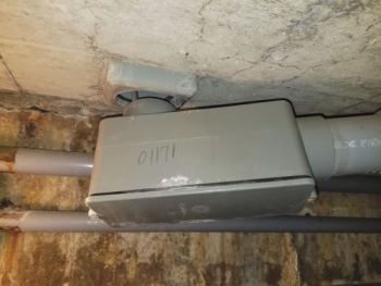
Figure 7: This photo shows PVC conduit in pool equipment tunnel. The conduit is suited to resist corrosion in this environment, but was broken at some point as people or equipment was moved through this area. Courtesy: Peter Basso Associates Inc.
Figure 7 is an example of damaged PVC conduit in a pool equipment area. Almost all metals corrode in a chlorinated environment, but in a properly maintained pool area, aluminum conduit should have a slow rate of corrosion as long as it not in contact with the water and should provide some additional mechanical protection for the wires and cables inside. Resin–based conduits could provide the advantage of both a nonmetallic raceway and mechanical strength similar to a metal conduit.
As with many things, there is no single best or correct selection, so the engineer should weigh the advantages and disadvantages of each potential option when selecting appropriate solutions.