Specifying the right electrical raceways, busways, wiring and cabling
Electrical and information cabling pathways are a vital component of any new or existing building.

Learning objectives
- Examine the basics of routing and protection for electrical and information cabling systems.
- Review different pathway systems such as raceways, cable trays, J-hooks, etc.
- Examine the application of surface–mounted raceways for building remodels and modernization projects.
Electrical and information cabling are an integral part of all building systems and must be extensively routed throughout all building types. There are several methods available for design teams to specify; however, catering a solution to specific applications is often difficult and convoluted.
As the buildings that we live, work, entertain and otherwise occupy become more complex and modern, there is an ever–increasing need to provide electrical and information infrastructure throughout. All buildings have a plethora of devices that require an electrical or data connection. Often these devices require a combination of each.
The end-use connection is often quite simple in either a direct connection or outlet type form factor; however, how is the wiring or cabling transported to this point? How is it protected from point to point? The answer: Using pathway systems that are permitted and practical for the specific structure or building space that transport the cabling safely to mitigate the risks of electrical shock, fire and other hazards related to personnel and property. To continue the description of the available systems, we must first identify the applicable standards and terms.
The governing code for all electrical pathways is NFPA 70: National Electrical Code, which dictates the uses permitted for the pathway systems and the terms used within the applicable standards. Information and communications technology cabling also are bound by the codes within the NEC, however there are applicable standards that take this a step further such as those set forth by the Building Industry Consulting Services International organization in its Telecommunications Distribution Methods Manual and the Telecommunications Industry Association and its applicable standards (commonly referenced as TIA-xxx, where xxx denotes a 3-digit number applicable to a specific document).
It is important to note that the NEC is an enforceable code that is meant to safeguard persons and property from the hazards arising from the use of electricity (NEC 90.1) and is a requirement; the standards surrounding ICT cabling are recommendations that optimize an ICT cabling system and are not safety related nor enforceable code.
Additionally, all pathway systems are listed by a nationally recognized testing laboratory for standards regarding fire rating, flame spread, use of products within air handling spaces (often referred to as plenums), etc. The most common NRTL is UL, which not only tests the products but also creates the applicable standards.
Types of wiring
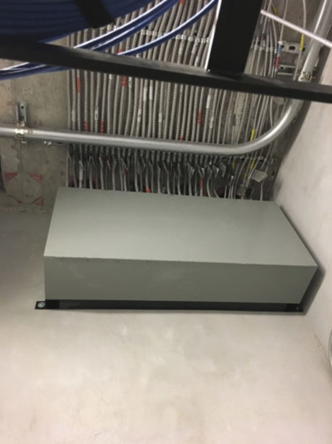
Figure 1: This is a gutter installed in a high-rise building that is provided as an accessible splice point. The level above is the serving electrical room and there are sections of EMT that connect into the top of the gutter. Within the gutter the contractor has spliced, via wire nuts, to connect to the horizontal runs of MC to horizontally feed the guestrooms. Courtesy: NV5
The first step to understanding any pathway system is to understand the wiring that is being transported and protected. The NEC delineates between several different types of wiring. We will examine the most common types of wiring: 1,000 volts or less, Class 1, Class 2 and Class 3 circuits. The NEC also sets code minimum requirements for conductors exceeding 1,000 volts.
Class 1 wiring typically is identified as remote-control or signaling conductors that are either power limited to 30 volts and 1000 volts-ampere (NEC 725.41(A)) or where the conductors are used for remote-control or signaling circuits (NEC 725.41(B)). When used for remote-control or signaling circuits, the voltage may be increased to 600 volts; however, these will typically be seen as 120-volt circuits that operate relays, motor controllers or similar control devices. Class 1 circuits are required to be routed in a pathway as established within chapter 3 of the NEC (NEC 725.46) and they may be routed through the same pathway system as a power feeder or branch circuit if the conductor insulation is rated for at least the maximum voltage available within the raceway system (NEC 300.3(C)(1)).
Class 2 and class 3 circuits are identified with the NEC chapter 9, table 11(A). Class 2 circuits are typically seen as low-voltage circuits that are limited to 30 volts or less and 100 volts-ampere or less. These class 2 circuits are considered protected from fire or shock due to low energy and voltage levels. Due to this, class 2 circuits are permitted to be installed in plenum areas (when properly listed) and are not required to be installed in raceway systems outlined within chapter 3 of the NEC. Class 2 circuits are most commonly seen as category cabling (as defined by TIA-568-C and is most commonly unshielded, balanced twisted pairs of wire that are designed for data transmission), wiring for public address systems, programmable logic controllers and thermostats.
Class 3 circuits are typically classified as circuits that exceed 30 volts but operate from 0.5 to 100 volts-ampere and are often used for sound/speaker systems, clock/intercom systems and security systems. Although beyond the breadth of this article, it should be noted that class 3 circuits can reach higher voltage and current levels under specific circumstances as outlined by NEC 725.121; however, it is less common. Class 2 and 3 circuits are not required to be installed in a pathway system as outlined within NEC Chapter 3 and may be routed through plenum spaces when using listed cabling and supports. These circuits may be routed in this manner as they are power limited or carry a low-energy signal that does not present a risk for the initiation of fire or shock.
Design considerations
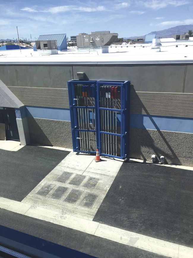
Figure 2: This installation shows a structural cage that has been constructed to add protection to the conduit. This installation is within a fire lane for an educational facility and fine metal mesh will be added to the installation to prevent access to the interior of the conduit cage when the hinged doors are closed and locked. Additionally, the existing building footing was compromised during excavation and a structural cage was required around the conduit to add structural integrity of the exterior wall. The conduit bodies are specialized to have manufactured large radius sweeps to prevent tight bending of ICT and fiber optic cabling. Courtesy: NV5
With the understanding of that cabling systems may require pathway systems outlined within chapter 3 of the NEC, we may now proceed to analyze the available pathway systems as well as their limitations and code requirements. There are several design considerations that need to be analyzed to provide the best pathway for a specific task. These considerations are: accessibility, pathway support requirements, distance that the pathway will travel, special protection requirements and the quantity of cables that must be transported.
Accessibility is one of the most important factors in any pathway system and is outlined in the NEC to require access to all junction boxes, gutters or splice points (NEC 314.29). Often, these pathways and boxes are installed above gypsum board or hard-lid ceilings where there is no practical way to reach the system without an access panel. When this type of a ceiling is used within a facility, it is critical to avoid system such as J-hooks and cable tray that are open and cannot be inspected to ensure that cabling is supported and secured. When not accessible, conduit or another type of raceway is the most practical choice.
Even with a raceway system, access panels will be required to access the following: a junction box for every 100 feet or every cumulative 180-degrees of bends for ICT cabling (TIA-569-D 9.8.2), a junction box for every cumulative 360-degrees of bends for line voltage wiring (for EMT NEC 358.26). In this aspect, the TIA standard is more stringent as it provides recommendations to ensure a minimum pulling force between access points is maintained. This ensures (as a rule of thumb) that the cable will not be subject to pulling tension in excess of the manufacturer’s recommendations and thus allow the cable to pass manufacturer’s field certifications and maintain signal integrity.
Often, junction boxes or gutters are used to provide a point to transition from electrical metallic tubing (type EMT) and wire to metal-clad cable (type MC cable) to traverse through inaccessible areas and route direct to the receptacles as required by the design (see Figure 1).
Often the ceilings or floors are accessible, such as with access floors or acoustic ceiling tile ceilings, commonly referred to as “lay-in” or “drop” ceilings. Where these types of building elements are installed, the designer has several choices for pathways that include additional options, as well as the raceway example previously presented.
Accessible building elements are advantageous where the systems need to accommodate moves, adds, changes and deletions (commonly referred to as MAC-Ds). Such building elements allow the use of cable trays (for power and ICT cabling) and J-hooks (ICT cabling). When installing these systems within a ceiling grid system such as ACT, it is imperative that the supports are not directly affixed to the ceiling grid supports (NEC 300.11(B)). The ceiling grid system should remain completely independent of all cabling, light fixture or other electrical systems.
When using a system such as a cable tray or J-hooks, the user may make changes to the cabling by removing ceiling tiles and simply laying a cable into the tray or J-hooks. Typically, these pathways are used in conjunction with conduit route within a wall to provide a connection to a junction box.
Another significant consideration for pathway systems is the required supports. Ideally, the best location for information on support requirements will be the manufacturer’s installation instructions and the NEC. The NEC specifically notes the support requirements for different raceway types within chapter 3, for example, EMT conduit shall be supported in increments of 10 feet and within 3 feet of every junction box, conduit body, etc. (NEC 358.30).
When reviewing the support requirements, unless specifically mentioned, the NEC does not make the distinction between horizontal and vertical support requirements. Some specific instances where the NEC does differentiate between vertical support requirements would be for industrial installations when using intermediate metal conduit (NEC 342.30(B)(2)) and rigid metal conduit (NEC 344.30(B)(2)). The NEC also defers the requirements for cable tray supports to the manufacturer’s installation requirements (NEC 392.30(A)).
If the electrical or ICT designer’s project is located within a seismic zone, additional requirements may be instituted and the support design may be required as a delegated design to a structural engineer. Additional conduit and cable options would be intermediate metal conduit (type IMC, NEC 342), rigid metal conduit (type RMC, NEC 344), fiberglass conduit (type RTRC, NEC 355), metal-clad cable (type MC, NEC 330) and each method has its specific application, support requirements and additional information that is all outlined within their respective NEC section.
Cable distance
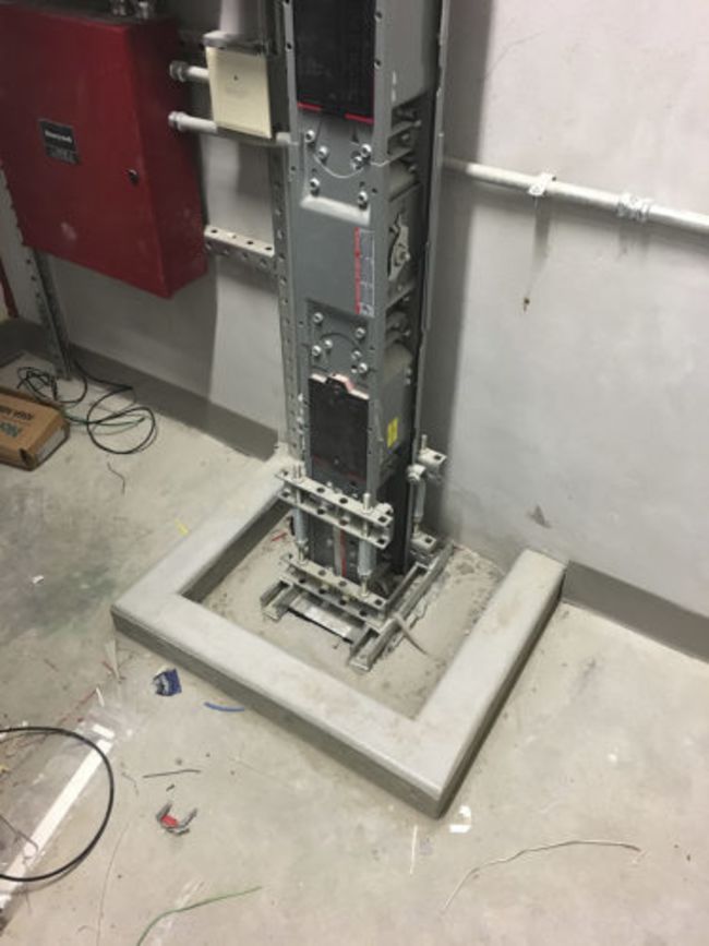
Figure 3: This is a vertical section of busway (or busduct) with no plug-on devices. The waterproof curb is visible in the bottom of the photo showing engineering supports bracing against the floor spanning the entire penetration. This has been sealed with intumescent material below the cover plate for fire protection between floors. Courtesy: NV5
When considering distance, it’s imperative to understand the cabling type that is being used. For line voltage power wiring, the main distance consideration is relative to the electrical load and the voltage drop that will be induced based on the wire’s impedance. The standard for voltage drop is outlined as a fine–print note for NEC 210.19(A), FPN No. 4. This FPN advises that branch circuits should be sized to prevent a voltage drop in excess of 3% and that feeders should be restricted to 2% voltage drop.
The FPNs within the NEC are not enforceable by a code official (NEC 90.5(C)); however, some jurisdictions may have enforceable energy codes that mandate a maximum voltage drop (most commonly ASHRAE Standard 90.1). When considering ICT premises wiring systems, it’s important to know the cabling media and the specific limitations associated with each type.
For example, category cabling is typically limited to 295 feet for the permanent link (wiring from the outlet to the patch panel or termination within the serving telecommunications space). However, if using fiber optic cabling, the distances vary based on fiber type (single-mode and multimode), the data transmission rate and the type of transceivers used. As the purpose of this article is not to examine the pros and cons of different ICT cabling, we will proceed with the more common Category-6 cabling standard (outlined to specific performance requirements within TIA-568-D) that limits this pathway to 295 feet.
When considering the aforementioned requirements, the pathway system will consist of either enclosed pathway (raceways) or open pathways (such as cable tray or J-hooks). While conduit and other enclosed pathways typically route directly to the receptacle or technology outlet location, an open pathway typically serves as an aggregation point, creating a less direct and often, longer path back to the serving equipment. Additionally, conduit may be used to collect cables to an aggregation point and if using the category cabling for power over ethernet applications, the NEC requires that you de–rate the current carrying capacity of the cabling by the coefficient shown within NEC table 725.144. These requirements must be considered primarily for ICT cabling.
When routing any type of cabling through a building, it is important to understand each space’s use and potential protection requirements. This extends from physical protection, to prevent mechanical damage, through fire protection or hazardous location requirements.
The first concept surrounding the subject of “physical damage” can be quite complex as no codes or standards clearly define the phrase, in fact, it is often conceded that this is subjective. Each authority having jurisdiction may approach this concept in different ways. On a basic level this should be applied in a common-sense approach where hard-use areas are treated with extra care for protection; it is important to note that the code intent is to prevent inadvertent physical damage and not to prevent damage from malice or intentional damage.
For example, hard–use areas should include but not be limited to: loading docks, enclosed sally ports for cash trucks, corridors with traffic of mechanical vehicles (pallet jacks, forklifts, etc.), mechanical rooms, gymnasiums, etc. Within these hard-use areas, the designer can defer to the uses permitted within chapter 3 of the NEC for pathways permitted in areas “subject to physical damage.” This would typically require a thick-walled conduit such as intermediate metallic conduit or galvanized rigid conduit in lieu of any types of tubing such as EMT or any open–type pathways such as cable trays (see Figure 2).
Fire protection and fire stopping
When considering fire protection requirements, the designer should first consult any available fire protection reports or code consultants for the project. Rated walls and enclosures will be identified in the fire protection report and on the architectural set of drawings. Often, a book or sheet specification can handle fire protection requirements and any seal off requirements for hazardous locations; however, the pathway requirements do change.
Within NEC 500 through NEC 503, there are additional requirements such as the requirement for threaded conduit systems (NEC 501.10(A)(1)(a) and NEC 502.10(A)(1)(a)) that also are required to be wrench tight to prevent a ground fault from arcing in an environment with flammable or explosive gases or dust (NEC 500.8(E)). Each classified area should be thoroughly examined for code compliance of all pathway (and miscellaneous electrical and ICT) systems. These identified areas also will be required to maintain the fireproof rating of the walls in that the pathway is penetrating.
In addition, where an open pathway is traversing through a plenum (or commonly referred to as an air handling space), a specialized plenum rated wiring method is required. A plenum rated cable is rated to burn within an air handling space and not introduce toxins or spread flame through the plenum; the mechanical designer for the project will identify plenum spaces that will assist the ICT designer to determine the cabling type required for the premises wiring system.
It should be noted by the electrical and ICT designers that a system designed to comply with NEC 645, Information Technology Equipment Rooms, may be exempt from the plenum rating requirement if the raised floor is used as a plenum rated space; the heating, ventilation and air conditioning is entirely separate of the building system HVAC; and there is a dedicated shunt trip for the electrical system and for the HVAC system (NEC 645.10).
Cable capacity and ampacity
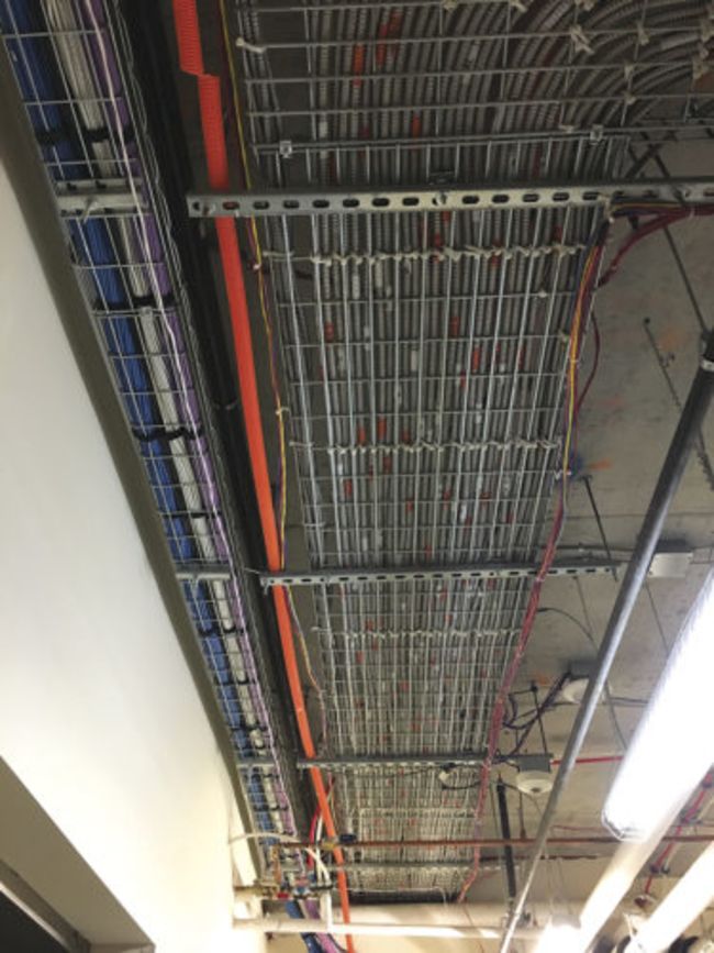
Figure 4: On the right, cable tray is used to support and secure MC wiring as a main routing point down the corridor. In the center, there is an orange innerduct that is used for fiber routing and on the left, there is a cable tray with cleanly segregated low-voltage cabling. Courtesy: NV5
As the electrical or ICT designer is identifying cabling types, available pathway routing and protection requirements, another consideration must be made for the ampacity or quantity of cables required. Electrical designers typically defer the cable routing to a “means and methods” process that involves the contractor’s judgment unless larger ampacity feeders, medium–voltage or utility routing is considered. When considering these larger ampacity installations, it is important that parallel feeder runs are routed in compliance with NEC 300.3(B)(1) and NEC 310.10(H) that requires that each parallel conduit run consist of an identical phase, neutral and ground conductor (as applicable). These parallel feeders must be of the same length, conductor material, size, insulation type and be terminated in an identical manner.
Often, when considering higher ampacity feeders or modular designs, it may be applicable to use busway. Busway is common for high-rise commercial hotel applications, industrial installations, larger data centers and greenhouse facilities. Large high-rise hotels typically are designed with a large ampacity busway installed vertically throughout the tower and plug-on units (specially designed disconnects or enclosed circuit breakers) are used for horizontal distribution feeders to panelboards.
Busways require a penetration through each floor of a tower and a fire protection report or code consultant should be consulted to discuss fire protection options for the room or penetration. Additionally, the NEC requires that the penetration is provided with a water-proof curb to prevent ingress of water and general flooding down the stacked electrical rooms (NEC 368.10(C)(2)(b)). If this waterproof curb is compromised, water may eventually work its way down the busduct and could result in a violent explosion due to a short circuit (see Figure 3).
When considering industrial, data center or grow facilities, it is not uncommon to see a combination of horizontal runs that are supplied with plug-on units to deliver load centers or 3-phase power at specific locations. This allows a modular design where power can be delivered in large ampacities throughout the run of busduct. This typically is catered to very specific owner and equipment requirements and can vary in application.
Although the depth of uses for busduct is beyond this article, it is a critical piece of any electrical designer’s arsenal and a minimum general understanding is required to provide the most efficient and thoughtful designs.
The analogy of large–ampacity installations for ICT designers would be the quantity of cables. Typically for large cable quantities an ICT designer will consider designing a cable tray layout with varying sizes that correlate to the quantity of cables at each junction or branch. This gives the primary horizontal cabling a support and routing backbone. These trays are sized in accordance with NEC 392 that has myriad complicated formulas and subsections that depend on tray type, cable type and ampacity (if applicable), to calculate a maximum fill percentage.
Instead of wading through this code section, often electrical designers will use a manufacturer’s cable tray calculation tools that are specifically programmed for compliance with the NEC. When discussing a cable tray consisting of only ICT cabling, a 40% fill ratio is recommended via the TIA-569-B standard. Typically, an ICT cable tray backbone is installed in a tapered manner in that the closer the installer is to the end use device or outlet, the smaller the cable tray; the closer the installer is to the serving telecommunications room, the larger the cable tray typically is. This is to accommodate the aggregation of cables within the cable trays.
With all the above considerations, an electrical or ICT designer should be knowledgeable and capable of applying all the above considerations to provide a code-compliant and practical design for a particular occupancy or building. Often the pathway system will consist of a combination of all the aforementioned (see Figure 4).
An example for ICT premises wiring system could include a cable tray with a fire rated penetration through a corridor wall that transitions to EMT above a hard–lid section of ceiling, only to transition back to cable tray once the routing reaches another accessible ceiling space. From here, the contractor may use J-hooks to route individual cables to specific technology outlets within each space. This would combine several types of pathways to provide the client or occupant a flexible system that is code compliant.
Definitions
Several key terms will need to be identified to clearly convey the requirements of the specific systems available to the system designers:
Busway (or busduct): A manufactured, enclosed pathway made of sheet metal with solid copper or aluminum busbars for higher ampacity installations in a compact footprint.
Cable tray: Nonenclosed tray type pathway designed to physically support premises wiring systems.
Pathway: Any physical method of supporting, enclosing, protecting or otherwise transporting wiring systems.
Premises wiring system: The wiring or cabling throughout a building, structure or compound downstream of the service connection or demarcation point.
Raceway: Any enclosed physical pathway designed to protect or shield premises wiring systems.